Disclaimer: This calculator has been tested in 2 different machine and different configurations and has performed correctly under those conditions. The double rotator is untested. However, it is provided "as-is" without any guarantee of accuracy or compatibility with all setups. Use at your own risk. The author is not responsible for any damage, loss, or incorrect results caused by use of this tool.
The user defines three points in the X-Y-Z coordinate system, and the code calculates the equation of the plane passing through them.
This allows us to determine how the plane is tilted relative to the original coordinate system.
The code calculates Δa and Δb, corresponding to tilts around the X and Y axes respectively, in accordance with G54.4,
the workpiece setting error compensation system.
The three points can be obtained, for example, by probing in the negative Z-direction on the surface of the part. If the plane is heavily tilted, it might be necessary to repeat
the probing and calculate corrections. Corrections calculations are below the plane inclination calculator. There is also more specific explanation below the calculators.
Enter 3 points in 3D space (x, y, z):
,
,
,
,
,
,
Below you can set plot's axis range and choose angled view. (optional)
Below you can apply second rotation (optional)
Loading Python...
Calculator Explanation
How This Calculator Works
We use a specific example to see the working principle of the calculator and the coordinate rotation in a CNC-machine. Let the workpiece
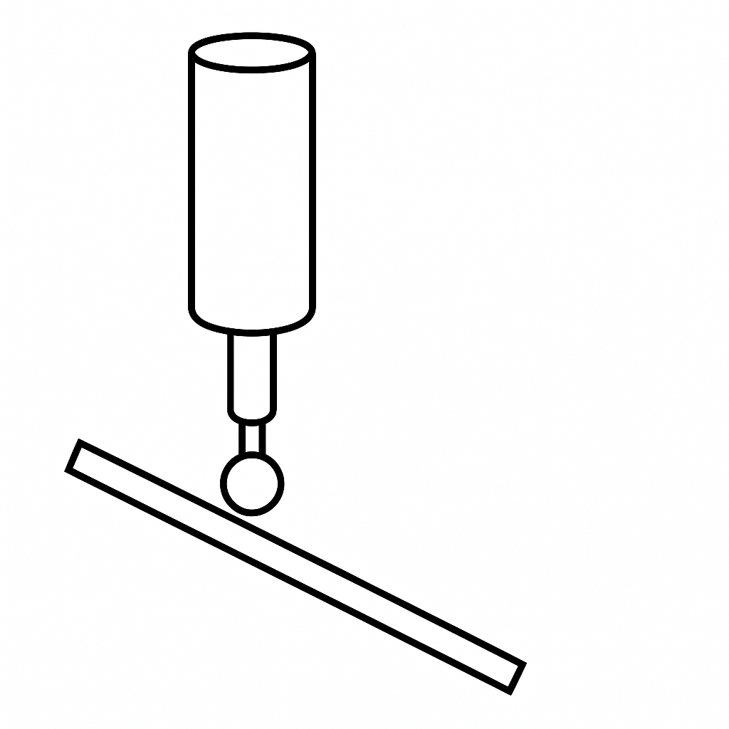
be secured on the table of the machine and we want to now know how it is oriented with respect the machines coordinate system. First we probe three
non collinear (not on the same line) points from the planar surface of the workpiece. Let us do that moving in negative Z-direction.
Probe Illustration
Plane Orientation and Normal Calculation
Plane can be tilted in any direction (and even simultaneously about multiple axes).
Now let the measured points be:
From these two vectors we form the \(3\times3\) matrix:
\[
M = \begin{pmatrix}
-34.7 & 9.1 & -9.274\\
-19.9 & 22.4 & 6.712\\
0.000 & 0.000 & 0.000
\end{pmatrix},
\]
and put it into reduced row echelon form:
\[
\mathrm{RREF}(M)
= \begin{pmatrix}
1.000 & 0.000 & 0.451\\
0.000 & 1.000 & 0.700\\
0.000 & 0.000 & 0.000
\end{pmatrix}.
\]
For the normal vector we can choose z-component and we choose it to be 1, so that the plane's normal points up in the machine. If you choose it to be negative it points down. Finally, a normal vector to the plane is extracted as:
\[
n = \bigl (-0.451,\,-0.700,\,1).
\]
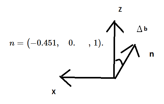
View along positive y axis and the projection of the normal vector
After we know how much the vector is rotated around y, we need to rotate it in reverse direction.
After the rotation, we calculate the rotation around x-axis, using the rotated vector.
So we rotate the normal vector by multiplying it with the rotation matrix Ry.
\[
\mathrm{Ry}(\phi)
= \begin{pmatrix}
cos(\phi) & 0 & sin(\phi)\\
0 & 1 & 0\\
-sin(\phi) & 0 & cos(\phi)
\end{pmatrix}.
\]
We use -Δb as an argument in rotation matrix. So we have to first calculata Δb.
\[
\Delta b = \arctan2\left(\frac{n_x}{n_z}\right)=\Delta b = \arctan2\left(\frac{-0.451}{1}\right) \approx -24.2^\circ
\]
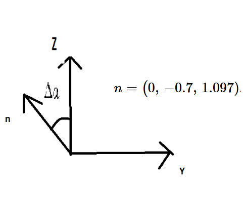
View along positive x axis and the projection of the normal vector
The code proceeds to calculate the tilt angle of the rotated normal vector:
\[
\Delta a = \arctan2(n_{y,\text{rotated}},\ n_{z,\text{rotated}})
\]
The sign of a rotation is determined by the right-hand rule: point your right-hand thumb in the direction of the rotation axis. The direction in which your fingers curl defines the positive rotation.
However, the arctan2 function gives the static orientation of the vector relative to the axis. To correctly interpret the original rotation angle, we must adjust the sign.
That’s why a negative sign appears in the formula for Δa.
\[
\Delta a = -\arctan2(n_{y,\text{rotated}},\ n_{z,\text{rotated}}) \approx 32.551^\circ
\]
G54.4 Offset Alignment and Re-Measurement
These are the values we write into the G54.4 OFFSET data table. After this is done, we can align the workpiece simply by calling:
G54.4 P1
G90 G0 B0. C0.
(Assuming P1 was used.) This can be executed in AUTO or MEMORY mode — note that MDI did not work in this case.
The G-command G0 moves the machine axis at high speed. One must ensure that the axis can move smoothly in the rotated orientation. This requires positioning the tool tip in a safe location so that no collisions occur and software limits are not exceeded during positioning.
Now, suppose the original measurement was inaccurate due to the heavy inclination of the plane or for some other reasons. In such cases, we can remeasure three points — but this must be done in the original coordinate system (not the rotated one), since G54.4 defines orientation relative to the original coordinates.
The 'apply rotation' button is for this. You can apply two successive rotations to have a correction if needed. One measurement is probably accurate enough.